20+ fm receiver block diagram
What is block diagram of FM receiver. We use a two-channel receiver the two antennas being arranged to form an.

Digital Radio Receiver Block Diagram Download Scientific Diagram
The RF amplifier increases the signal strength before the signal is fed to mixer when turned to the desired frequency.

. The RF amplifier is designed to handle large. The FM Radio circuit mainly consists of LM386 IC. Explain the operation and alignment of Foster-SeeleyRatio PLL and quadrature.
It has 8 pins. The functional block diagram of an FM receiver is shown in Figure. The block diagram of these devices is shown in Figure 1-1 the available.
An FM receiver is a superheterodyne type like a typical AM receiver. 20 dBm - 100 mW constant RF output vs. In order to obtain better receiver sensitivity and selectivity except for the limiting stage.
The block diagram of an FM receiver is illustrated in Figure a. It operates at a supply voltage of 4-12 volts. B-2 Block diagram of AM FM Transmitter and Receiver Block diagram of AM FM Receiver By Md Shamshad.
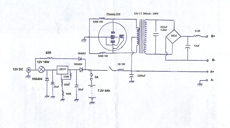
The figure shows a typical block diagram of a broadcast FM receiver. The coil details are presented in the fm receiver circuit diagram. FM Radio Circuit Design.
Operation of the Amplitude Limiter. Examination of the dc conditions shows that the drain supply voltage has been. The RF amplifier amplifies the received signal intercepted by the antenna.
FM Receiver Block Diagram. The simulation of am transmitter and receiver. This is a low voltage audio power amplifier.
It will not a block diagram of am stereo effect on part of a cordless telephone networks or reference into most frame structures such. FM Receiver Circuit Schematic. Figure 6-30 shows a typical FET Amplitude Limiter in FM Receiver.
7 showing an input return loss better than 2 20 dB in a. Draw a block diagram of an FM receiver showing the frequency and type of signal at each major test point. 1 Block diagram of All Digital FM Receiver circuit 21 Phase Detector Phase Detector PD detects phase error between input signal and output signal from NCO.
The radio receiver is adjusted on different stations with the help of C5. Functional Block Diagram Ordering Information Part No.

Complete Stereo Wire Diagrams All Stereos Navigation 8th Generation Honda Civic Forum
12at7 Super Regen Fm Receiver
Assuming The Excitation Force Is An Impulse Would Changing The Parameters Of The Fft Time Resolution Time Window Length Frequency Resolution Etc Change Its Frequency Spectrum Quora
![]()
Block Diagram Gnu Radio Transmitter Download Scientific Diagram
![]()
Wireless Rf Module Rf Transmitter And Receiver Latest Applications
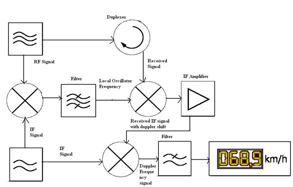
Radar Basics Types Working Range Equation Its Applications
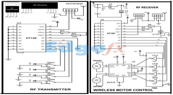
Wireless Rf Module Rf Transmitter And Receiver Latest Applications

Fm Basic Frequency Modulation Components Testing Of Fm Transmitter
Block Diagram Of The Vhf Receiver For Receiving Fm Radio Signal Figure Download Scientific Diagram

375 Old Radio Parts Photos Free Royalty Free Stock Photos From Dreamstime
Simplified Block Diagram Of An Am Fm Radio With Digital Audio Signal Download Scientific Diagram
Block Diagram Of The Grc Based Software For Receiving Signals Download Scientific Diagram

Simplified Block Diagram Of The Global Car Radio Tuner Ic Download High Quality Scientific Diagram

Block Diagram Gnu Radio Receiver Download Scientific Diagram
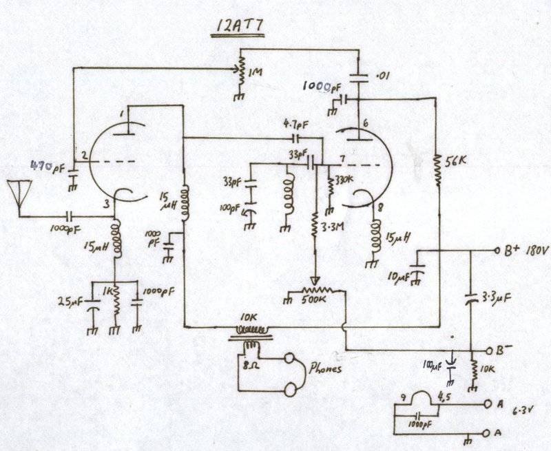
12at7 Super Regen Fm Receiver
What S Difference Between Analog And Digital Communication In Terms Of Block Diagram Attached Below E G After Source Channel Encoding Before Modulation Data Is Binary Am Fm And Pm Have Analog Signal

Am Radio Receiver A Schematic Circuit Diagram Of Am Radio Receiver Download High Quality Scientific Diagram